Metallic Plasma Generator
Project Manager : Dr. Marian MOGILDEA
Team
members: Dr. George MOGILDEA, Dr. Emil STAN
, Drd. Florin MINGIREANU, Drd. Iulia JIVANESCU. Drd.Gabriel CHIRITOI.
Electric propulsion has been an intense area of research since the 1960s,
and it has benefitted great theoretical and experimental research. Electric
propulsion is used for both maneuvering Earth orbiting satellites and for
interplanetary missions due to its high specific impulse and lower thrust when
compared to its chemical counterpart.
The initial status of the electric propulsion is mainly
represented by systems that use gas or liquid propellant, such as Xenon, Argon,
Helium – in the case of Hall thrusters, ionic thrusters, etc. Gaseous
propellants pose some disadvantages as they have a high ionization energy, are
expensive and they need a large reservoir for storage.
Taking in consideration the existing limitations of these space
propulsion systems the science community is looking at ways of increasing the
efficiency of the existing propulsion systems or at developing new thruster
technologies. As a response, our proposed model aims to increase the efficiency
of the electric thrusters by using heavy metals as propellants.
The main goal of our proposal is to develop an
experimental setup entitled the Metallic Plasma Generator (MPG), based on a new technology of
vaporization and ionization of a metal wire (lead) using a microwave field. It
is well known that the microwave radiation is reflected by metallic objects,
but in certain cases, the microwave radiation is absorbed by metals which
results in metal vaporization.
This new space electric technology would be a highly efficient type of
propulsion, given by the physical properties of the metal used as propellant. A
metal can become fuel for electric space propulsion systems only if it is
vaporized, ionized and its metallic ions accelerated. By using the heavy metal
Pb as propellant the MPG experimental setup will have the following advantages:
·
low electrical power consumption due to the fact that the Pb atoms have a low ionization energy (the great
majority of actual space electric propulsion systems use Xenon as propellant,
which has a high ionization energy, high cost)
·
low volume and low weight (comparative
with actual technology where a reservoir is used for storing the gaseous
fuel, the MPG will not encounter this
issue, as Pb has high density and low volume)
·
high efficiency, given by the large atomic weight of Pb
The main
objectives of the project are represented in the table below:
|
Main objectives |
Activities |
|
1.
Documentation and
analysis of the interaction of the microwave radiation with matter |
1.1 Microwave generation and propagation - It will
theoretically analyze how the microwave field is propagated in cylindrical
waveguides having the TM011, TM012 and TM010
propagation modes, in order to find the most suitable waveguide for the
MPG. |
|
1.2 Microwave interaction with metals – will lead to
understanding the dependency between the
different microwave powers of the cylindrical waveguide and the quantity of
vaporized and ionized metal; it will analyze the influence of different metal
wire diameters on the quantity of vaporized and ionized metal. Theoretical
computing will take place in order to determine the energy density of the
microwave radiation in the focal point of the cylindrical waveguide. |
|
|
1.3 Defining the
experiment requirements |
|
|
2.
Design of the
experimental setup |
2.1 Design of the cylindrical waveguide for
the 2.45GHz frequency - the cylindrical
waveguide is the ionization chamber where the metallic propellant will be vaporized and
ionized by the microwave field |
|
2.2 EM Power Supply Design – aimed to have over 90%
efficiency, a variable output frequency (25Hz – 400Hz) and pulse duration variable (1ms -20ms). It
also enompasses the design of the system cooling for the electromagnetic
source (magnetron + electronic board), which will ensure the optimal
temperature for operating the microwave source and the electronics in vacuum
conditions. |
|
|
2.3 Design of the injector propellant – a system composed of mechanical
and electronics subcomponents, which will push a reel of thin metallic wire
(the solid propellant) in the high density energy region of the waveguide. |
|
|
2.4 Design of the plasma acceleration system –
it will design the grids
necessary for plasma acceleration |
|
|
2.5 Design of the plasma characterization and
measurement system |
|
|
2.6 Preliminary planning |
|
|
3.
Development of the
experimental setup |
3.1 Development of the cylindrical waveguide -
for 2.45GHz
frequency |
|
3.2 Development of the EM Power Supply |
|
|
3.3 Development of the injector propellant |
|
|
3.4 Development of the plasma acceleration system |
|
|
3.5 Integration of the experimental setup |
|
|
3.6 Preliminary experimental setup
functionality tests –tests in vacuum conditions in order to investigate
the optimal gas quantity necessary for the MPG setup. The optimal gas
quantity will be used together with metal wires in order to work as
propellant. |
|
|
3.7 Optimization of the experimental setup |
|
|
4.
Experiment running and
characterization |
4.1 Metallic Plasma Diagnostics – Information referring
to electron
temperature, plasma density, plasma potential and metallic ions speed . |
|
4.2 Report on experimental results |
Design Metallic Plasma Generator:
The metallic plasma generator consists of an electronic system for feed and control on the microwave source, the microwave source (commercial magnetron) and a cylindrical cavity (fig. 1). In the cylindrical cavity a metal wire is introduced in the microwave field. As a result of the absorption of the microwave field, the metallic wire will vaporize, and the vapors will be ionized.
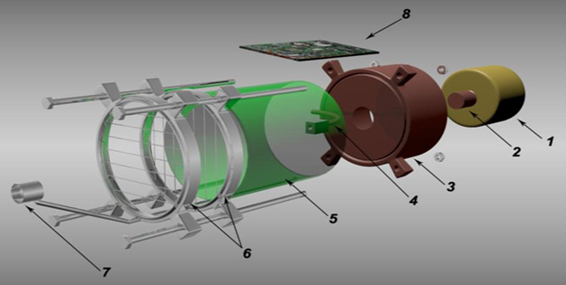
Fig.1 The
main components of the MPG:
1- magnetron,
2- magnetron antenna, 3- cooling system, 4- pipes for propellant (metal wire
and gas), 5- cylindrical waveguide, 6
–acceleration system, 7 – electron emitter, 8- electronic part of the metal
injector system
Metallic Plasma Generator
Experimental Model
In order to study the microwave absorption process by metallic wires we conducted a MPG experimental system. The experimental model contains a microwave plasma generator, a power source, a Faraday cage, and an exhaust system of the metallic vapors (fig. 2).
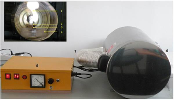
Fig.2
Metallic Plasma Generator experimental model:
1- plasma,
2- metallic wire, 3- ceramic support, 4- plastic support, 5-power supply, 6-
Faraday cage, 7- exhaust system,
8- duty
factor control of the HV the from anode
magnetron.
The power source of the Microwave Metallic Plasma Generator Experimental Model consists of three power sources, two low voltage sources (DC), one for the magnetron filament and one for the exhaust system of the metal vapors. The third power source feeds the anode magnetron with high voltage electric impulses (~4KV). The impulse repetition frequency is 50 Hz. The length of the impulses ranges between 1ms and 20 ms. The quantity of the vaporized metal is controlled by an electronic module. This modifies the length of the electric impulses (duty factor) of the source that feeds the anode magnetron. If the duty factor varies between 20 % and 100 % the power of the generated microwave radiation modifies between 20 W and 800 W. Therefore, by modifying the duty factor of the electric signal applied on the anode magnetron, we modify the quantity of the vaporized metal.
Experimental
Results:
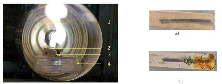
Because in metals the microwave absorption mechanism is characterized only by ohmic losses, in our experiment the microwave absorption by metallic wires is revealed through the vaporization process of the metal wires as a result of their interaction with the microwave field. In order to observe the results of the microwave field on metallic wires, we exposed Pb wires with 0.5 mm diameter and 4 cm length in the microwave field. In order to determine the quantity of vaporized metal the microwave power was set to 150W, 300W and respectively 600W.
|
Fig. 3. The lead sample is vaporized
and ionized by the microwave field in the cylindrical waveguide: 1- metalic
plasma, 2- lead sample, 3- ceramic support, polycarbonate support. |
Lead wire samples: a - before exposure
in cylindrical cavity, b - metallic wires after exposure in cylindrical
cavity |
Table 1 presents how the vaporized and ionized quantity of metal depends on the microwave field from the cylindrical cavity.
|
The
metal wire (0.5
mm diameter) |
The
microwave power (W) inside
the cavity |
The
quantity of vaporized and ionized
metal (mg/s) |
Melting
point ( |
Electrical
resistivity (Ω∙m) at 20℃ |
|
Lead |
150 |
3.6 |
327.46 |
|
|
300 |
38 |
|||
|
600 |
43 |
Table 1
Results dissemination:
Ø Investigation of the absorption processes of the microwave radiation by metal wires, ISI article in press.
Ø Direct vaporization and ionization of the metals wires using microwave field, ISI article in press.
Ø Scientific Conference - Bucharest University Faculty of Physics 2014 Meeting
Ø G. Mogildea, M. Mogildea, Experimental investigation of the metals vaporization and ionization with microwave used as propellant for ionic propulsion, Journal of Optoelectron. Adv. Mater. – Rapid Communication, Vol.4. No.3, pp 352-356 ,2010.
Ø M. Mogildea, G. Mogildea, Experimental investigation of the metals vaporization
and ionization with microwave used as propellant for ionic propulsion, Journal of Optoelectron. Adv. Mater. Vol.12, No.5, pp 1157-1160,2010.
Ø G. Mogildea, M. Mogildea, Experimental investigation of the microwave electrothermal thruster using metals as propellant, Journal of Optoelectron. Adv. Mater. – Rapid Communication, Vol.4. No.11, pp 1826-1829 ,2010.
This
project is supported by the Romanian Space Agency through (STAR) Space
Technology and Advanced Research Programme (project No. 90/2013).